

🛠️ Preparation

Tools Required
- Ratchet with Sockets(8/10/13mm)
- Extensions & Wrenches
- Needle Nose Pliers(Crucial)
- Electrical Tape
- Wire Cutter/Stripper (Optional)
Box Contents
See Photo
- Running Boards (x2)
- Linkage Assemblies (x4)
- Hardware Kit
- Harness & ECU
- LED Lights
⚙️ Bracket & Motor Installation
1
Pre-Assemble Brackets
- ● Attach the mounting brackets to the linkage arms before putting them on the truck.
- ● Fasten the linkage arms using M8 Flanged Nylon Lock Nuts.
- ● Note: Tighten these fully now.
2
Install Driver Side Brackets
- ● Locate the mounting studs on the rocker panel (under the doors).
- ● Place a Plastic Insulator (F) over each stud first. This prevents corrosion and noise.
- ● Mount the Front Bracket Assembly (A) and Rear Bracket Assembly (B) onto the studs.
- ● Note: Do not fully tighten these nuts yet; leave them snug but adjustable for alignment.
⚡Power & ECU Setup (Engine Bay)
3
Battery & Fuse Safety
-
●
Open the hood. Remove the 25A fuse from the Main Harness fuse holder.
Do not skip this step (Safety against shorting). - ● Connect the Power Leads: Red (+) to Positive, Black (-) to Negative battery terminals.
-
●
Connect the ECU to the Main Harness.
Secure the ECU near the battery using zip ties. Ensure it is mounted away from high-heat engine components.
4
Routing the Harness
- ● Route the Main Harness (M) along the firewall and down the Driver-side wheel well.
- ● Route the shorter leg of the harness down the Passenger-side wheel well.
- ● Note: Use zip ties to secure wires away from hot or moving engine parts.
5
Penetrate to Cabin (Signal Wires)
- ● Under the driver's side floor (behind the front wheel), locate the rubber floor grommet.
- ● Poke a small hole through the grommet.
- ● Thread the two signal wires (from the harness) up into the vehicle cabin.
- ● Inside the truck, remove the driver's side kick panel and door sill plate. Peel back the carpet to locate the wires you just fed through.
🔌Deep Dive: Signal Wiring Guide (BCM Connection)

2. Insert: Slide the Main Harness signal wire into the narrow channel.
3. Secure: Use needle-nose pliers to press the metal blade down firmly. It must pierce the insulation of both wires to make a connection.


Make or Break: This step allows the running boards to "read" your door signals. Please follow carefully.
A
Locate & Identify
- ● Locate: Find the OBD-II Port under the steering wheel, near the front hood release lever.
- ● Access: Unbolt the two flanged nuts using a socket for easier access to the rear side of the plug.
- ● Identify Wires: From the rear side of the connector, identify the Grey with Orange Stripe wire and Purple with Orange Stripe wire.
B
Connection Guide
See Photos
| Signal | Factory Wire | Main Harness |
|---|---|---|
| CAN HIGH | Grey/Orange | White |
| CAN LOW | Purple/Orange | Yellow |
How to use Shark Taps:
1. Clamp: Place the factory wire inside the wider channel of the tap.2. Insert: Slide the Main Harness signal wire into the narrow channel.
3. Secure: Use needle-nose pliers to press the metal blade down firmly. It must pierce the insulation of both wires to make a connection.
⚠️ NOTE:
Make sure the wire is seated properly in the jaws before clamping. The wire must be centered on the "teeth". After connecting, return the connector back into its place and tighten the nuts.
×
![]()
🔩 Final Assembly
7
External Connections
- ● Install LED Lights: Peel the adhesive backing and stick the LED lights to the rocker panel underside. Plug them into the harness.
- ● Connect Harnesses: Under the vehicle, connect the Main Harness to the LED Y-Harnesses on both sides.
- ● Plug in Motors: Connect the Y-Harness to the front motor plugs.
8
Mounting the Boards
-
●
Power Up:
Re-insert the 25A fuse.
Open the door to extend arms.
Unplug the motor to cut power and keep brackets down for installation. - ● Mount Boards: Slide (4) M6 Carriage Bolts into the channels. Align with bracket slots. Secure with Washers and Nuts. Adjust position and tighten all nuts.
- ● Reconnect: Plug the motor connector back in (or re-insert fuse). Close the door to retract the steps.
✅ Final System Check
Cycle Test: Open and close each door multiple times to ensure the steps deploy and retract smoothly without binding.
Check Hardware: Double-check that all mounting bolts are tightened to spec.
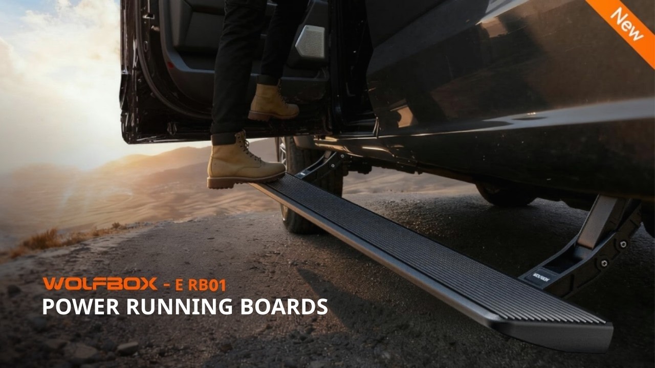
General Install (See Manual for Specifics)
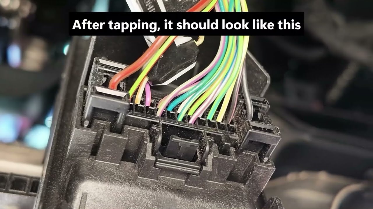
How to Locate the CAN Bus Port | 2020-2022 Ford F-250-550 (SYNC 3)
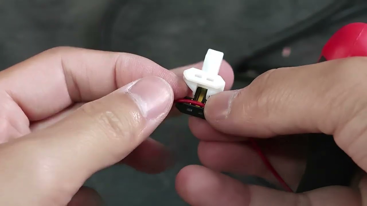
How to Use Shark Taps for CAN Bus Wiring | Power Running Board Installation
How to Use Shark Taps for CAN Bus Wiring | Power Running Board Installation
F-250/F-350/F-450/F-550 Super Duty (2020-2022)
Download
It’s fully automated. The boards deploy when the door opens and retract when the door closes. We use advanced CAN bus technology to read door signals directly, eliminating the need for unreliable magnetic switches.
Absolutely. They are built for it. All components, including the IP67-rated motor and connectors, are weatherproof and sealed tight. They are tested from -40°F to 176°F to ensure flawless performance.
We built them strong! Each side has a proven load capacity of up to 660 lbs. Feel free to load up your gear or stand side-by-side with a buddy—they can take it.
Yes. The 6-inch wide platform features an aggressive textured surface designed to provide maximum grip, even with wet or muddy boots.
Yes, there is! Integrated LED lighting automatically illuminates the step surface when the board extends, dramatically improving visibility and safety for those late-night entries.
Safety first! Our boards include an auto-stop anti-pinch function that instantly halts movement if an obstruction is detected. Plus, there’s a 3-second safety delay before retraction just to give you extra peace of mind.
Nope! That’s the beauty of them. When retracted, the boards fit snugly against the vehicle body, ensuring you maintain your maximum ground clearance for optimal off-road capability.
No drilling required. This is a 100% bolt-on installation. Our brackets utilize the designated factory mounting points on your truck’s frame. Check out our installation video above for a detailed walkthrough specific to your vehicle.
